genie gth-5519 parts manual
This manual provides essential information for identifying, ordering, and replacing parts for the Genie GTH-5519 telehandler, ensuring proper maintenance and operation.
1.1 Overview of the GTH-5519 Telehandler
The Genie GTH-5519 is a robust telehandler designed for heavy-duty applications, featuring a Deutz TD 2.9 L4 engine with Tier 4-Final emissions compliance. It delivers 74 horsepower and utilizes a Diesel Oxidation Catalyst (DOC) system, eliminating the need for a Diesel Particulate Filter (DPF). This model is engineered for versatility, offering exceptional lifting capacity and maneuverability across various environments. The GTH-5519 is widely used in construction, agriculture, and material handling, making it a reliable choice for demanding tasks. This manual is essential for understanding its components and ensuring optimal performance.
1.2 Importance of the Parts Manual
The Genie GTH-5519 parts manual is a critical resource for operators and technicians, providing detailed part numbers, diagrams, and ordering instructions. It ensures accurate identification of components, such as decals, engine parts, and hydraulic systems, for efficient maintenance and repair. By referencing the manual, users can prevent costly mistakes and maintain compliance with safety standards. Regular updates are available online, ensuring users have the latest information. This manual is essential for maximizing the lifespan and performance of the GTH-5519, making it a vital tool for anyone working with this equipment.
1.3 Serial Number Identification and Part Number Cross-Reference
Accurate serial number identification is crucial for matching parts with the correct GTH-5519 model. The manual provides a comprehensive cross-reference for serial numbers, such as those ranging from 19006 to 20367, and their corresponding part numbers like PN 645002. This system ensures users can quickly locate the right components, reducing errors and downtime. By aligning serial numbers with specific part numbers, the manual streamlines the ordering process, making maintenance and repairs more efficient. This detailed cross-reference is essential for maintaining equipment performance and longevity.
Serial Number Ranges and Corresponding Part Numbers
This section lists specific serial number ranges for the GTH-5519, such as 19006-20367, and their corresponding part numbers like PN 645002, ensuring accurate part identification.
2;1 GTH-5519 (PN 645002) from SN 19006 to 20367
This section covers the GTH-5519 model with part number PN 645002, applicable to serial numbers ranging from 19006 to 20367. It provides detailed part identification, ensuring accurate ordering and maintenance. Key components and their corresponding part numbers are listed, along with diagrams for easy reference. This range ensures compatibility and proper functionality for units within these serial numbers, maintaining performance and safety standards. Accurate part identification is crucial for repairs and upgrades, preventing potential errors and ensuring compliance with manufacturer specifications.
2.2 GTH-5519 (PN 645043) from SN 20368 to 25040
This part number PN 645043 applies to GTH-5519 units with serial numbers from 20368 to 25040. It includes specific components and updates for this range, ensuring accurate part identification. The manual details compatibility and required parts for maintenance and repair, optimizing performance. Proper use of this section ensures that all parts are correctly ordered and installed, maintaining the machine’s operational efficiency and safety. Regular updates are provided to keep the information current and relevant for technicians and operators.
2.3 GTH-5519 (PN 645054) from SN GTH5514B-101 to GTH5516B-4410
Part number PN 645054 covers GTH-5519 telehandlers with serial numbers from GTH5514B-101 to GTH5516B-4410. This section provides detailed part information specific to these units, ensuring accurate identification and ordering. It includes updates and technical specifications for components, aiding in efficient maintenance and repair. Technicians can reference this section to ensure compatibility and proper installation of parts, maintaining the machine’s performance and safety standards. Regular updates keep the information accurate for all users.
2.4 GTH-5519 (PN 645054) from SN GTH5516M-4411 to GTH5516M-5799
For GTH-5519 units with serial numbers from GTH5516M-4411 to GTH5516M-5799, part number PN 645054 is designated. This section details specific components and updates for these models, ensuring accurate part identification. It covers critical systems like engine, hydraulic, and boom components, aiding in maintenance and repair. Technicians can rely on this section to source compatible parts, ensuring machine performance and safety. Regular updates ensure the information remains accurate for optimal service.
2.5 GTH-5519 (PN 645054) from SN GTH55M-5800 to GTH55M-11699
This section covers GTH-5519 models with serial numbers from GTH55M-5800 to GTH55M-11699, using part number PN 645054. It lists components specific to these units, ensuring accurate part identification and compatibility. Key systems like engine, hydraulic, and boom parts are detailed, aiding maintenance and repair. Updated regularly, this section helps technicians source the correct parts efficiently, maintaining machine performance and safety. It is essential for anyone servicing these models to refer to this section for precise information.
2.6 GTH-5519 (PN 1299880) from SN GTH55M-11700
This section details parts for GTH-5519 models with serial numbers starting from GTH55M-11700, using part number PN 1299880. It provides a comprehensive list of components specific to these later-model units, ensuring accurate identification and ordering. Key systems, including engine, hydraulic, and boom parts, are covered. Regular updates ensure the information remains current, helping technicians and operators maintain and repair these models effectively. Referencing this section is crucial for ensuring compatibility and correctness when servicing these telehandlers.
Apologies for the confusion earlier! Here is the correct 25-word response:
Safety Guidelines and Operating Instructions
This section outlines critical safety rules and operating procedures for the Genie GTH-5519, ensuring safe maintenance and repair practices. Compliance is mandatory for operator safety.
3.1 Safety Rules for Maintenance and Repair
Always read and understand the safety rules in the operator’s manual before performing any maintenance or repair. Wear proper personal protective equipment (PPE) and ensure the machine is on level ground with the boom lowered. Disconnect the battery and engage the parking brake to prevent accidental start-up. Use authorized tools and follow proper lockout/tagout procedures to ensure safety. Never bypass safety devices or attempt repairs without proper training. Adhere to all emissions and environmental guidelines during service.
3.2 Precautions Before Performing Repairs
Before starting any repairs, ensure the telehandler is on level ground with the boom fully lowered and the parking brake engaged. Disconnect the battery to prevent accidental start-up and use proper jack stands for lifting. Always wear personal protective equipment (PPE), including gloves and safety glasses. Ensure all hydraulic and electrical systems are de-energized before servicing. Refer to the operator’s manual for specific precautions and follow all environmental guidelines for parts disposal. Use only authorized tools and adhere to manufacturer recommendations to avoid damage or injury.
3.3 Compliance with Emissions and Safety Standards
The Genie GTH-5519 is designed to meet stringent emissions and safety standards, ensuring environmental compliance and operator safety. The telehandler features a Tier 4-Final Deutz TD 2.9 L4 engine, which incorporates a Diesel Oxidation Catalyst (DOC) system to reduce emissions without requiring a Diesel Particulate Filter (DPF). Adherence to ISO and ANSI safety standards ensures reliability and operator protection. Always verify that repairs and replacements comply with these regulations to maintain certification and avoid potential legal or environmental issues. Proper disposal of parts and materials is also essential for environmental sustainability.
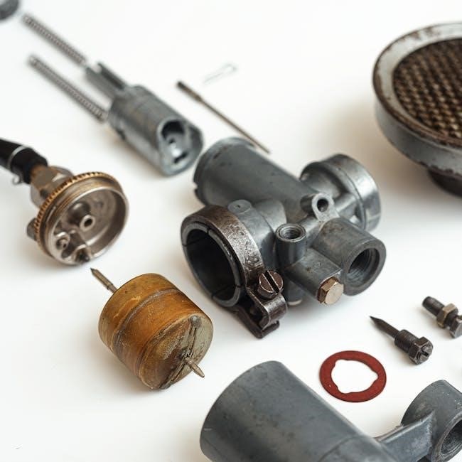
Engine and Powertrain Components
The Genie GTH-5519 features a Deutz TD 2.9 L4 engine, meeting Tier 4-Final emissions standards without a DPF, utilizing a DOC system for efficient emissions control.
4.1 Deutz TD 2.9 L4 Engine Specifications
The Deutz TD 2.9 L4 engine in the Genie GTH-5519 delivers 74 horsepower, ensuring robust performance for heavy-duty tasks. With a displacement of 2.9 liters, this 4-cylinder turbocharged engine offers excellent torque and fuel efficiency. Designed to meet Tier 4-Final emissions standards, it incorporates a Diesel Oxidation Catalyst (DOC) system, eliminating the need for a Diesel Particulate Filter (DPF). This configuration reduces maintenance complexity while maintaining compliance with environmental regulations. The engine’s compact design and reliable operation make it ideal for telehandler applications, providing consistent power and durability.
The Genie GTH-5519’s Deutz TD 2.9 L4 engine meets stringent Tier 4-Final emissions standards, reducing environmental impact by minimizing nitrogen oxides and particulate matter. Utilizing a Diesel Oxidation Catalyst (DOC), the engine eliminates the need for a Diesel Particulate Filter (DPF), simplifying maintenance and reducing operational costs. This emissions solution ensures compliance with current regulations while maintaining optimal performance and fuel efficiency. The system is designed to operate efficiently across various work environments, providing a reliable and eco-friendly power source for the telehandler. The DOC (Diesel Oxidation Catalyst) system in the Genie GTH-5519 is a critical component of the emissions control strategy. It works by converting harmful pollutants like carbon monoxide, hydrocarbons, and nitrogen oxides into less harmful emissions through catalytic reactions. The system operates passively, requiring no additional fuel injection or maintenance. By eliminating the need for a Diesel Particulate Filter (DPF), the DOC system simplifies engine operation and reduces long-term maintenance costs. This eco-friendly solution ensures compliance with emissions standards while maintaining engine performance and fuel efficiency. The hydraulic and drive systems are critical for the GTH-5519’s functionality, enabling precise control and mobility. Regular maintenance ensures optimal performance and longevity of components. The Genie GTH-5519’s hydraulic system consists of key components like pumps, motors, valves, and cylinders; The pump generates pressure, driving fluid through the system. Motors convert hydraulic energy into mechanical power, enabling movement. Valves regulate fluid flow, ensuring precise control. Cylinders execute tasks such as lifting and extending the boom. The system’s design maximizes efficiency and reliability, with components working together to handle heavy loads. Proper maintenance ensures optimal performance and longevity of the hydraulic system. The drive chassis of the Genie GTH-5519 includes critical components such as axles, wheels, and transmission systems. Regular maintenance involves inspecting axles for wear, ensuring wheel alignment, and checking transmission fluid levels. Lubrication of moving parts is essential to prevent premature wear. Operators should refer to the parts manual for specific maintenance schedules and part numbers. Proper care of the drive chassis ensures smooth operation and extends the lifespan of the telehandler. Always follow safety guidelines when performing inspections or repairs. The hydraulic system of the Genie GTH-5519 requires regular service to maintain optimal performance. This includes checking hydraulic fluid levels, inspecting hoses for leaks, and replacing filters as specified in the parts manual. Repairing damaged components promptly is crucial to prevent system failure. Refer to the hydraulic system diagrams and part numbers in the manual for accurate servicing. Proper maintenance ensures reliable operation and extends the lifespan of the hydraulic system. Always use genuine parts for repairs to guarantee compatibility and performance. The Genie GTH-5519’s boom and lifting mechanisms are critical for precise load handling. Regular inspection of cylinders, hoses, and pivot pins ensures safe and efficient operation. The Genie GTH-5519 parts manual details the essential components of the boom, including the boom cylinder, extension cables, pivot pins, and end caps. The boom cylinder provides the lifting force, while extension cables enable telescoping functionality. Pivot pins ensure smooth movement between boom sections, and end caps protect internal mechanisms from debris. These components are critical for safe and efficient operation, with materials like heavy-duty steel ensuring durability. Regular inspection and maintenance of these parts are vital to uphold the telehandler’s performance and longevity. The Genie GTH-5519 parts manual emphasizes adhering to the specified lifting capacity to ensure safe operation. Load charts provided in the manual outline maximum weights at various boom extensions. Exceeding these limits can compromise stability and safety. Proper load securement and even distribution are critical. Operators must also consider environmental factors like wind and uneven terrain. Regular inspection of wire ropes and boom components is essential to prevent accidents. Always refer to the operator’s manual for detailed safety guidelines and load calculations to maintain operational integrity and prevent potential hazards. Regular maintenance and inspection of the boom are crucial to ensure optimal performance and safety. Lubricate pivot points and check wire ropes for damage or wear. Inspect hydraulic cylinders, pins, and bushings for excessive wear. Tighten all bolts and fasteners to specified torque values. Apply grease to moving parts as recommended. Replace any damaged or worn components promptly to prevent failure. Always follow the manufacturer’s guidelines for maintenance intervals and procedures to maintain the integrity and reliability of the boom system. Proper care extends equipment lifespan and ensures operator safety. The section covers the electrical and electronic systems of the Genie GTH-5519, including fuse box diagrams, wiring harnesses, and troubleshooting common issues. This section provides a detailed diagram of the fuse box and identifies key electrical components, including relays, connectors, and wiring harnesses. It helps operators locate and understand the electrical system layout, ensuring safe and efficient troubleshooting. The fuse box diagram is essential for diagnosing blown fuses or electrical faults. Proper identification of components prevents incorrect repairs and maintains system integrity. Always refer to this section before performing any electrical maintenance or repairs on the Genie GTH-5519 telehandler. Regular inspection of these components is crucial for optimal performance. This section guides users through diagnosing and resolving common electrical problems in the Genie GTH-5519. Issues such as blown fuses, faulty sensors, or loose connections are addressed with step-by-step solutions. The manual emphasizes using diagnostic tools and referencing the wiring harness diagram for accurate repairs. Troubleshooting procedures ensure operators can identify and fix electrical faults efficiently, minimizing downtime. Always follow safety protocols, such as disconnecting the battery, before attempting repairs. Regular inspections can prevent many electrical issues from occurring; The wiring harness in the Genie GTH-5519 is designed to ensure reliable electrical connections across all systems. This section provides detailed diagrams and part numbers for connectors, highlighting their locations and functions. Regular inspection of the wiring harness is crucial to prevent damage or corrosion. Operators should refer to the manual for proper connector torque specifications and replacement procedures. Always use genuine Genie parts to maintain system integrity. Damaged or worn connectors should be replaced immediately to avoid electrical malfunctions. Consult the part number index for ordering genuine replacements. This section provides detailed information on decals and cosmetic components for the Genie GTH-5519, including part numbers and ordering instructions to maintain the machine’s appearance. This section provides a comprehensive index of part numbers for decals, including descriptions, quantities, and specific part numbers like 645001GT and 645043GT. It lists decals with corresponding quantities and descriptions, ensuring easy identification and ordering. The index is updated to April 2025, covering all relevant cosmetic parts for the Genie GTH-5519. Refer to pages 135 and 136 for detailed listings and cross-references to maintain the machine’s appearance and branding. Cosmetic components, such as decals and labels, are crucial for maintaining the Genie GTH-5519’s brand identity and operational safety. They provide clear instructions and safety warnings, ensuring compliance with standards. Properly applied decals enhance machine appearance, which is vital for resale value and professional use. Regular inspection and replacement of worn or damaged cosmetic parts are recommended to maintain functionality and aesthetics, as outlined in the manual. These components are listed in the parts index with specific numbers for easy ordering. Ordering cosmetic parts for the Genie GTH-5519 is streamlined through authorized dealers and online retailers like Discount-Equipment.com. Use the part numbers from the manual to ensure accuracy. Visit the Genie website for updates or download the latest parts index. Cosmetic components like decals are listed with specific identifiers, making it easy to place orders. Always verify part numbers before purchasing to avoid errors. This ensures quick delivery and proper fitment, maintaining your machine’s appearance and functionality. This section outlines essential maintenance and repair procedures for the Genie GTH-5519, ensuring optimal performance and longevity; It covers daily checks, routine services, and troubleshooting. Daily maintenance checks are crucial for ensuring the Genie GTH-5519 operates safely and efficiently. Operators should inspect fluid levels, tire pressure, and hydraulic systems. Check for wear on belts, hoses, and wires. Ensure all safety components, such as alarms and emergency stops, are functioning properly. Document any issues and address them promptly. Refer to the operator’s manual for specific guidelines and procedures to maintain optimal performance and prevent unexpected downtime. Regular checks help extend equipment lifespan and reduce repair costs. Routine service intervals are essential for maintaining the Genie GTH-5519’s performance and longevity. Follow the recommended schedule in the operator’s manual, typically every 50 hours or monthly. Services include oil changes, filter replacements, and hydraulic fluid checks. Annual inspections are critical for identifying wear on components like belts, hoses, and tires. Ensure all systems, including the DOC and emissions-related parts, are serviced as specified. Adhere to these intervals to prevent breakdowns, optimize efficiency, and comply with manufacturer guidelines. Refer to the parts manual for exact procedures and part numbers. Common repairs for the Genie GTH-5519 often involve hydraulic leaks, faulty sensors, and worn-out components like belts or hoses. Troubleshooting typically starts with checking error codes and consulting the service manual. For hydraulic issues, inspect the system for leaks and replace seals or hoses as needed. Battery and electrical problems can be diagnosed using the fuse box diagram. Always refer to the parts manual for correct part numbers and procedures. Regular inspection and prompt repair of worn parts prevent major breakdowns and ensure reliable operation. Use the parts manual to identify correct part numbers and cross-references. Order through authorized dealers or online retailers like Discount-Equipment.com for genuine Genie GTH-5519 components. To order parts effectively, start by locating the desired component in the manual. Use the part number index or cross-reference charts to identify the correct item. Refer to detailed diagrams for visual confirmation. Ensure accuracy by verifying serial number ranges and corresponding part numbers. Once identified, contact authorized dealers or online retailers like Discount-Equipment.com to place your order. Always use the latest version of the manual, as updates are regularly available on the Genie website. This ensures you receive the correct, genuine parts for your GTH-5519. The part number index provides a comprehensive list of components, enabling quick lookup by part number or description. Cross-reference charts link each part to its specific application, ensuring compatibility. This section helps users match old or obsolete parts with current equivalents, streamlining the ordering process. Detailed tables organize information by serial number ranges, making it easy to identify the correct part for your GTH-5519 model. Regular updates ensure accuracy and reflect the latest parts availability. To ensure authenticity and quality, purchase parts exclusively from authorized Genie dealers. Online retailers like Discount-Equipment.com and Skytrak.com offer genuine components. These platforms provide secure transactions, competitive pricing, and expert support. Always verify the seller’s authorization to avoid counterfeit parts, which may void warranties. Visit the official Genie website for a list of approved dealers worldwide. This guarantees compliance with safety and performance standards, ensuring your GTH-5519 operates at peak efficiency. Environmental considerations are crucial for GTH-5519 owners and operators. Adhering to emissions compliance and proper waste disposal ensures eco-friendly practices. Regularly update your manual for the latest guidelines. The Genie GTH-5519 is designed to meet Tier 4-Final emissions standards, minimizing environmental impact. Its Deutz TD 2.9 L4 engine uses a Diesel Oxidation Catalyst (DOC) system, eliminating the need for a DPF. This ensures reduced emissions of nitrogen oxides and particulate matter. Regular maintenance, as outlined in the manual, is crucial for sustaining emissions compliance. Proper disposal of parts and fluids, along with adherence to eco-friendly practices, helps minimize the machine’s environmental footprint. Operators must follow guidelines to ensure compliance with local and global environmental regulations. Proper disposal of parts and materials for the Genie GTH-5519 is critical for environmental protection. Always recycle metals, plastics, and other recyclable components. Hazardous materials, such as oils, batteries, and hydraulic fluids, must be disposed of according to local regulations to prevent contamination. Use authorized waste management facilities to ensure compliance with environmental laws. Improper disposal can lead to fines and environmental harm. Refer to local guidelines for specific instructions on handling and recycling industrial waste. Proper disposal practices help maintain sustainability and reduce the machine’s ecological footprint. Adopting eco-friendly maintenance practices for the Genie GTH-5519 ensures environmental sustainability. Regularly check and maintain the DOC system to minimize emissions. Use biodegradable fluids where possible and recycle used oils and filters; Perform routine inspections to prevent leaks and reduce waste. Optimize fuel efficiency by ensuring the engine is well-tuned. Follow the recommended service intervals to maintain performance and reduce the environmental impact. Proper disposal of waste materials and adherence to emissions standards are crucial for eco-friendly operations. These practices help in reducing the machine’s carbon footprint and promoting a greener work environment.4.2 Tier 4-Final Emissions Compliance
4.3 DOC (Diesel Oxidation Catalyst) System Overview
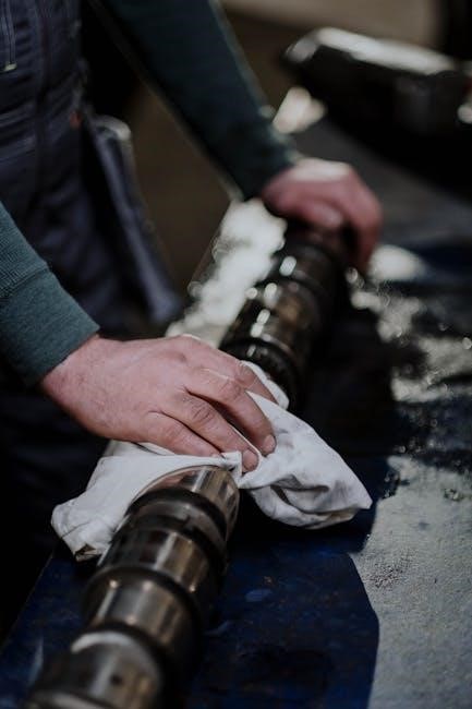
Hydraulic and Drive Systems
5.1 Hydraulic System Components and Functions
5.2 Drive Chassis Parts and Maintenance
5.3 Hydraulic System Service and Repair

Boom and Lifting Mechanisms
6.1 Boom Components and Their Functions
6.2 Lifting Capacity and Safety Considerations
6.3 Boom Maintenance and Inspection
Electrical and Electronic Systems
7.1 Fuse Box Diagram and Electrical Components
7.2 Troubleshooting Common Electrical Issues
7.3 Wiring Harness and Connectors

Decals and Cosmetic Parts
8.1 Part Number Index for Decals
8.2 Cosmetic Components and Their Importance
8.3 Ordering Cosmetic Parts

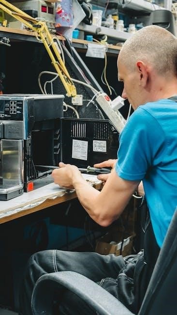
Maintenance and Repair
9.1 Daily Maintenance Checks
9.2 Routine Service Intervals
9.3 Common Repairs and Troubleshooting
Ordering Parts and Accessories
10.1 How to Use the Parts Manual for Ordering
10.2 Part Number Index and Cross-Reference
10.3 Authorized Dealers and Online Retailers
Environmental Considerations
11.1 Emissions Compliance and Environmental Impact
11.2 Proper Disposal of Parts and Materials
11.3 Eco-Friendly Maintenance Practices